piACC-Mini-Min-V6
Forums:
V6
Mini-Min is now completed (sans 3d printed wrapper)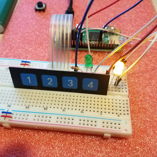 This will probably end up being the unit that I use in my Jeep.
On my last venture to MicroCenters I was able to pick up a few of the "four button touch" pads.
Nicely, the ribbon cable plugs directly into the GPIO using the top row, last 5 pins.(Ground,GPIO,GPIO,GPIO,GPIO)
I had some serious difficulties getting it all to work code-wise though. Python code worked every time, however the service failed each time.
I put in a 1 second delay which it seems to like better, but yet another second added to boot/ready.
Being limited to only 4 buttons however caused another problem. Not enough buttons for reboot and shutdown of the unit.
I added code for a combo-button press which got me over that hurdle.
Buttons 1-4 control relays 1-4.. nice.
I also added an LED (yellow) to display "blue tooth connected" and another LED (green) to display "some light is on".
For combination buttons, if you press two buttons within 1 second (hopefully not accidentally) it will evaluate them as a command.
Command Buttons
1 & 3 = reboot the button controller.1 & 4 = shut down the button controller.
2 & 3 = Sends reboot command to the relay controller.
2 & 4 = Sends shut down to the relay controller.
This should keep the unit quite minimal in size.
The 4 button pad will be mounted length-wise with the pi zero, it is almost the exact length/width dimension-wise as the pi with the GPIO header.
Direct solder minus the header is an option but this way seems much easier and I would still need pins for the pad ribbon cable.
A backup of the micro SDC and this one is finished and ready for use.
- Log in to post comments